
How Does the Forging Process Turn Steel Billets into Finished Industrial Parts?
September 18, 2026
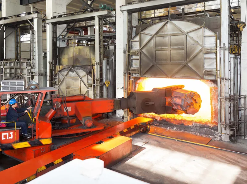
The forging process converts steel billets, bars, and other metal stock into shaped industrial components through controlled plastic deformation. A typical route includes material selection, cutting, heating, preforming, forging, trimming, heat treatment, machining, and inspection. The actual sequence varies with steel grade, component geometry, production volume, tolerances, and forging method.
Open die forging uses relatively simple dies and progressive deformation. Closed die forging uses shaped cavities to guide material into a defined geometry. Upset forging, roll forging, and radial forging serve more specific forming requirements.
For industrial procurement, forging should be viewed as a complete manufacturing route. The forging stroke represents only one part of production. Material preparation influences consistency before forming. Heating affects plasticity and metallurgical condition. Tool geometry controls material flow. Heat treatment establishes required mechanical properties. Machining creates critical final dimensions.
These factors directly affect tooling investment, material utilization, machining allowance, production capacity, lead time, and inspection requirements.
Understanding the complete forging process gives engineering and purchasing teams a stronger basis for evaluating suppliers. It also makes technical discussions around drawings, materials, tolerances, quantities, and inspection plans more productive.
What Are the Main Stages of the Forging Process?
Industrial steel forging normally follows a planned sequence from incoming material to finished inspection.
A common production route includes:
- Steel grade and raw material selection
- Billet or bar cutting
- Billet preparation and weighing
- Controlled heating
- Preforming or upsetting
- Main forging operation
- Trimming or excess material removal
- Heat treatment
- Surface cleaning
- Machining
- Dimensional and material inspection
Not every component requires all these operations. A large shaft may follow an open die route with several deformation steps. A shaped automotive or machinery component may require preforming and multiple closed die stages.
ASM International identifies material characteristics, tooling, friction, temperature, equipment, and deformation conditions as important forging variables.
The manufacturing route should therefore be established before production begins. Process planning connects the finished drawing with the actual sequence used on the shop floor.
1. Steel Material Selection
Production starts with a steel grade that matches the component requirements.
Common choices include carbon steel, alloy steel, stainless steel, and other engineering grades. Each material responds differently to heating and deformation.
Material specifications normally define chemical composition, mechanical properties, applicable standards, and supply condition.
Starting stock also requires consideration. Depending on the part, the supplier may use round bar, square bar, billet, bloom, slab, or large ingot.
Stock dimensions influence forging reduction and material utilization. They also affect the amount of material available for machining after forming.
Traceability should begin at this stage. Heat numbers and material certificates can connect incoming steel to subsequent forging, heat treatment, and inspection records.
For critical industrial components, maintaining this traceability throughout production provides a clear quality-control framework.
2. Billet Cutting and Preparation
Once the material has been approved, the stock is cut into suitable forging blanks.
Billet weight depends on several factors. These include finished part weight, machining allowance, forging method, flash allowance, and expected material loss.
Closed die forging requires sufficient material to fill the die cavity. An undersized billet may produce incomplete filling.
Excess material creates other consequences. It can increase flash formation, trimming work, and material consumption.
Open die forging requires a different calculation because the operator progressively changes the dimensions of the workpiece.
Cutting accuracy also matters. Consistent billet dimensions help maintain repeatable forging conditions across production batches.
Process engineers therefore determine billet dimensions as part of the overall forging design rather than treating cutting as a separate purchasing decision.
3. Controlled Heating
Steel requires an appropriate temperature range for hot forging.
Heating reduces the material’s resistance to deformation. It allows the workpiece to undergo substantial plastic deformation without excessive forming loads.
Temperature control remains critical throughout the operation.
Excessive heat can increase oxidation, surface deterioration, grain growth, and other metallurgical risks. Insufficient heat can raise forging loads and reduce material workability.
Industrial forging facilities may use gas-fired furnaces, electric furnaces, induction heating, or combinations of heating systems.
The selected method depends on material, billet dimensions, production volume, required temperature control, and forging equipment.
Large workpieces may also experience substantial temperature differences between the surface and core. Process planning must account for these conditions.
ASM International identifies temperature as one of the major variables affecting forging behavior. Temperature control therefore forms part of both process engineering and quality management.
How Does Deformation Turn Heated Steel into a Forged Component?
After reaching the required temperature, the workpiece enters the forming stage.
Forging equipment applies compressive forces through dies, tools, rolls, or other forming systems. Instead of removing material, the operation redistributes solid metal into the required shape.
That distinction separates forging from machining.
Machining removes material from a larger workpiece. Forging changes the shape of the existing material through plastic deformation.
As a result, a forged component can provide a near-net starting geometry for later machining.
The selected forming method depends heavily on size, geometry, material, production quantity, and required dimensional control.
Open Die Forging
Open die forging uses relatively simple dies rather than a fully enclosed cavity.
The workpiece remains accessible during deformation. Its position can change between individual forging operations.
Common operations include upsetting, drawing out, reduction, and controlled section changes.
Large shafts, discs, blocks, rings, and similar components often use open die processes.
ASM International describes open die forging as a process based on repeated deformation and controlled material flow. The final component normally includes machining allowances and dimensional tolerances.
Consider a large industrial shaft as an example.
A billet may begin with a substantial cross-section. Repeated reductions can decrease its diameter while increasing its length. Additional forging operations can establish different sections, shoulders, or diameter transitions.
Machining then creates bearing seats, keyways, threads, and other precision features.
This route provides flexibility for large components without requiring a dedicated full-shape cavity.
Closed Die Forging
Closed die forging uses shaped cavities to control material distribution.
The heated billet enters the die set, where compressive forces push material into the required cavity.
Complex components often require several forming stages instead of one final stroke.
A typical sequence may include:
- Billet preparation
- Initial upsetting
- Preform forging
- Blocker forging
- Finishing forging
- Trimming
Preforming distributes material before the final cavity. This becomes important when the finished component contains large and small sections within the same geometry.
Poor initial distribution can increase the risk of underfill, laps, excessive flash, or uneven deformation.
Tooling design therefore needs to consider the entire forming sequence rather than only the final cavity.
Upset Forging
Upset forging increases the cross-sectional area of a selected section.
At the same time, the affected portion becomes shorter.
This approach suits components that require localized enlargement. Fasteners, pins, shafts, and similar parts can use upsetting operations.
The process may form one stage within a larger production sequence.
Engineering attention should focus on material movement and workpiece stability. Excessive deformation in one direction can create buckling or other forming problems.
Roll and Radial Forging
Roll forging uses rotating rolls to progressively reduce and shape the workpiece.
Radial forging applies repeated deformation around the workpiece, usually through multiple tools or dies.
Both processes can support specific geometries and production conditions.
Roll forging can suit elongated components and controlled section reduction. Radial forging can support shafts, tubes, and other rotationally symmetrical parts.
Equipment capability, material, component dimensions, and annual quantity all influence process selection.
Other specialized routes include orbital forging and related forming techniques. Each method creates different deformation patterns and equipment requirements.
Which Variables Control Forging Quality?
Forging quality depends on the interaction between material, temperature, tooling, equipment, lubrication, and deformation.
Changing one variable can affect several others.
A die design suitable for one steel grade may require adjustment for another. Likewise, a heating schedule that works for one component may not suit a larger or more complex geometry.
Process development should therefore evaluate the complete forming system.
Die Geometry and Draft
Tool geometry controls how material moves during deformation.
Closed die cavities must provide enough space for the steel to fill the required features. Transitions, radii, draft angles, flash lands, and parting lines all influence forming behavior.
Sharp transitions can restrict local material flow.
Small radii can concentrate deformation and increase tooling stress.
Insufficient material distribution can cause underfill or laps.
The finished CAD model also does not directly represent the complete forging die.
Tooling may require additional geometry for draft, flash, machining allowance, trimming, and die separation.
These features help connect the customer’s final component geometry with a manufacturable forging route.
Friction and Lubrication
Contact between hot steel and tooling creates friction.
That friction affects material flow, forging load, die temperature, and surface condition.
Lubrication can modify the interface between the workpiece and die. The appropriate lubricant depends on material, temperature, forging method, tooling, and equipment.
ASM International identifies friction as an important variable in forging operations.
For closed die forging, controlling the interface can help maintain predictable material movement through the cavity.
Lubrication should therefore form part of process development rather than being treated only as a production consumable.
Temperature During Deformation
Workpiece temperature changes throughout forging.
The steel loses heat during transfer, die contact, deformation, and pauses between operations.
Large components can experience additional temperature differences because their cores cool more slowly than their surfaces.
Such changes affect deformation resistance and process consistency.
Multiple heating stages may become necessary for large or complex forgings.
Temperature measurement should occur at appropriate points within the production route. Critical applications may also require documented temperature records.
A controlled thermal cycle supports repeatability across production batches.
Material Flow
Material flow describes how the steel moves as forming forces act on the workpiece.
The deformation pattern should match the intended component geometry.
Closed die forging depends heavily on preform design. The preform establishes the material distribution before the finishing cavity.
Open die forging relies more heavily on the sequence and amount of individual reductions.
Heavy sections require particular attention because deformation may not distribute uniformly across the entire cross-section.
Process engineers therefore consider geometry, reduction, temperature, tooling, and material behavior together.
What Operations Follow the Main Forging Stage?
A forged blank rarely becomes a finished industrial component immediately after forming.
Downstream operations establish mechanical properties, surface condition, dimensional accuracy, and inspection status.
The exact route depends on the drawing and material specification.
Trimming and Flash Removal
Closed die forging can create flash around the component.
Trimming removes this excess material after the main forming operation.
The trimming tool must match the forged geometry.
Incorrect alignment or excessive force can damage edges and affect dimensions.
After trimming, the component can move to heat treatment or other specified operations.
Heat Treatment
Heat treatment adjusts the metallurgical and mechanical condition of forged steel.
Common treatments include normalizing, annealing, quenching, and tempering.
Selection depends on steel grade, required hardness, tensile strength, toughness, microstructure, and service conditions.
A controlled heat-treatment cycle normally includes defined temperature, holding time, and cooling conditions.
Different steel grades require different treatment parameters. The supplier should therefore establish the cycle against the relevant material standard.
Heat-treatment records can also support production traceability for critical components.
Surface Cleaning
Hot forging and heat treatment can leave oxide scale on the component surface.
Shot blasting and other cleaning methods can remove surface deposits.
The appropriate method depends on component geometry, material, surface requirements, and subsequent operations.
A clean surface also supports visual examination and dimensional measurement.
Surface cleaning may therefore serve both production and inspection purposes.
Machining
Forging establishes the general shape, while machining creates critical final features.
Common machining operations include:
- Turning
- Milling
- Drilling
- Boring
- Grinding
- Threading
Machining allowance should be considered during forging design.
Too little stock can make it difficult to remove surface irregularities or achieve final dimensions. Excessive stock increases machining time and material removal.
Closer forged geometry can reduce machining requirements, but tighter forging control may require additional tooling and process development.
The practical objective is to balance forging accuracy against machining, tooling, and production costs.
Inspection
Inspection verifies whether the completed component meets the drawing and applicable specifications.
Depending on the application, inspection may cover:
- Dimensional accuracy
- Surface condition
- Chemical composition
- Hardness
- Tensile properties
- Microstructure
- Ultrasonic testing
- Magnetic particle testing
- Other non-destructive testing
Inspection requirements should reflect actual component risk and service conditions.
A general machinery component may require dimensional and material verification. A critical load-bearing component may require additional NDT and mechanical testing.
How Does the Forging Process Support Custom Steel Parts?
Custom forging begins with the finished component rather than a predetermined machine route.
Engineering teams must connect the drawing with material selection, billet size, deformation sequence, tooling, heat treatment, machining, and inspection.
A defined forging procedure brings these elements into one production route.
Example: Custom Steel Shaft
Consider a steel shaft used in industrial machinery.
The drawing may specify several shaft diameters, shoulders, bearing seats, keyways, and threaded sections.
Starting stock must provide sufficient material for the complete forged geometry.
An open die process may establish the primary shaft dimensions through upsetting and drawing operations.
Heat treatment then develops the required mechanical properties.
CNC turning creates the main diameters and bearing surfaces. Milling can produce keyways. Grinding may establish tighter surface and dimensional requirements.
Final inspection verifies the critical dimensions and specified material properties.
The example shows how forging and machining serve different purposes. Forging establishes a structurally suitable starting form. Machining creates the precision interfaces.
Example: Custom Forged Lever
A forged lever can require a different route.
Its geometry may include an integrated body, arm, boss, transitions, and connection points.
Closed die forging can establish much of this shape within dedicated tooling.
Preforming distributes material before the final cavity. Finishing forging establishes the main geometry. Trimming removes flash.
Heat treatment then develops the required material condition.
Machining can create holes, bores, or other critical interfaces.
Compared with machining the entire component from bar stock, the forging route can reduce the amount of material that must be removed.
The suitable process depends on geometry, quantity, material, and production requirements.
Custom forging therefore describes a project requirement rather than one specific forming method.
Submit your drawings and production requirements to FWD Forgings for a forging process assessment.
How Should Industrial Buyers Select a Forging Process?
Procurement teams should evaluate forging as part of the complete manufacturing cost and quality structure.
Unit price alone does not explain the economics of a forged component.
Material utilization, tooling, machining, heat treatment, inspection, production quantity, and lead time can all affect the final cost.
| Selection Factor | Questions to Ask | Typical Process Implication |
|---|---|---|
| Material | What steel grade and specification apply? | Determines heating and deformation conditions |
| Component size | What are the finished dimensions and weight? | Large sections may favor open die routes |
| Geometry | How complex is the required shape? | Complex geometry may favor closed die forging |
| Production quantity | How many parts are required annually? | Higher volume can support dedicated tooling |
| Tolerances | Which dimensions require close control? | May increase tooling or machining requirements |
| Machining | Which surfaces require final machining? | Influences forging stock and process design |
| Mechanical properties | What strength and toughness are required? | Affects deformation and heat treatment |
| Inspection | Which tests are specified? | Determines quality-control planning |
| Tooling | Is dedicated tooling economically justified? | Depends on quantity and component geometry |
| Lead time | When are production parts required? | Tooling and process development affect schedules |
Caption: Key factors for selecting a forging process for industrial steel components.
Production Quantity and Tooling
Production volume has a major influence on tooling economics.
A dedicated closed die requires engineering, machining, setup, maintenance, and qualification work.
For a small production run, these costs can represent a significant portion of total manufacturing expense.
High-volume programs distribute the tooling investment across more components.
Flexible open die routes may therefore suit some lower-volume or large-component projects.
The correct comparison should consider expected lifetime quantity rather than only the first purchase order.
Component Size and Equipment Capacity
Large forgings require equipment with adequate forming force and workpiece handling capacity.
Required forging force depends on material, temperature, geometry, deformation, tooling, and process conditions.
Equipment selection also involves more than hammer or press capacity.
Large workpieces may require manipulators, cranes, turning systems, transfer equipment, and specialized tooling.
A supplier should confirm the complete equipment route before accepting a large forging project.
Tolerances and Machining
Forging does not eliminate the need for machining.
Bearing surfaces, holes, threads, keyways, sealing interfaces, and other critical features commonly require machining.
Drawings should distinguish between forged dimensions and final machined dimensions.
That distinction helps engineers establish suitable machining allowances.
It can also prevent unnecessary attempts to achieve machining-level tolerances directly through forging.
Material Utilization
Material utilization affects both cost and production efficiency.
A billet that is too small can cause forming problems. Excessive stock can increase flash and machining requirements.
Closed die forging also produces flash that requires trimming.
Open die forging may involve different material losses because the process progressively changes the workpiece.
Billet optimization should therefore consider the entire manufacturing route.
What Types of Industrial Components Can Be Forged?
Forging supports a wide range of industrial component geometries.
The appropriate route depends on component dimensions, material, production volume, mechanical requirements, and tolerances.
Forged Products for Machinery
Industrial machinery can use forged shafts, hubs, pins, levers, brackets, gears, couplings, and other mechanical components.
Large shafts may use open die forging.
Smaller shaped components can use closed die processes.
Heat treatment and machining then establish the required mechanical and dimensional condition.
Forged Steel Parts for Heavy Equipment
Construction, mining, material handling, and other heavy equipment can require components exposed to repeated mechanical loading.
Examples include:
- Shafts
- Pins
- Hubs
- Links
- Coupling components
- Drive components
- Mechanical structural parts
The forging route should reflect the component’s actual load conditions.
Material selection should address strength and toughness requirements.
Inspection should also correspond with the consequences of component failure.
Custom Metal Forgings
Custom metal forgings generally begin with a customer drawing or technical specification.
The supplier develops the production route around the required geometry and material.
That route can include billet preparation, forging, tooling, heat treatment, machining, and inspection.
A custom metal forging manufacturer should connect these stages through one coordinated manufacturing plan.
This approach simplifies technical communication when a project requires multiple downstream operations.
Heavy-Duty Forged Components
Large shafts, discs, rings, hubs, and other mechanical parts can fall into the heavy-duty forging category.
However, the term should not stand alone as a technical specification.
Actual requirements should define the expected operating conditions.
Relevant parameters can include:
- Applied load
- Fatigue conditions
- Impact exposure
- Operating temperature
- Hardness
- Tensile strength
- Toughness
- Dimensional requirements
- Required service life
Open die forging often suits large components with flexible geometries.
Closed die forging can suit smaller, repeatable components with defined shapes.
The process should follow measurable engineering requirements rather than a general product label.
How Can Forging Quality Be Controlled Across Production?
Quality control starts before the first forming operation.
A complete quality plan should connect material receipt, process parameters, heat treatment, machining, and final inspection.
Incoming Material Control
Material should match the specified steel grade and applicable standard.
Heat numbers should remain traceable throughout production.
Material certificates should correspond to the actual incoming stock.
Additional chemical or mechanical verification may apply to critical projects.
Forging Process Control
Billet dimensions should remain consistent.
Heating should follow the defined temperature range.
The forging sequence should follow the approved process.
Tooling condition also requires regular monitoring.
Closed dies can change dimensions through wear.
Open die tools can influence surface condition and dimensional consistency.
Process records can help identify variation between production batches.
Heat-Treatment Control
Heat treatment requires controlled furnace conditions.
Temperature, holding time, atmosphere where applicable, and cooling conditions should follow the approved specification.
Records should connect the treatment cycle with the relevant production batch.
Hardness and other mechanical tests can then verify the resulting material condition.
Final Inspection
Final inspection should compare the component against the drawing and applicable standards.
Dimensional checks can cover diameters, lengths, angles, hole locations, and other critical features.
Surface inspection can identify visible defects.
NDT requirements depend on component design and service conditions.
Ultrasonic testing can evaluate internal discontinuities in suitable components. Magnetic particle testing can identify certain surface and near-surface discontinuities in ferromagnetic materials.
The inspection plan should therefore be established from the component’s actual technical requirements.
What Questions Should You Ask a Forging Supplier?
What information is needed for a forging quotation?
A supplier normally needs the component drawing, steel grade, annual quantity, order quantity, tolerances, mechanical requirements, heat-treatment requirements, inspection standards, surface requirements, and delivery expectations.
Providing complete information reduces assumptions during process development.
Should the supplier quote forging and machining separately?
That depends on the sourcing strategy.
A forging-only quotation can be useful when machining remains under the customer’s control.
A combined forging and machining quotation can simplify procurement when the supplier provides both operations.
Comparing both routes can clarify the actual total manufacturing cost.
When does closed die tooling become worthwhile?
Tooling economics depend on production volume, component geometry, material, die complexity, and expected program life.
Higher production quantities generally provide more units over which tooling costs can be distributed.
A supplier should calculate tooling against expected lifetime production.
Can a large component use closed die forging?
Component size can impose practical limitations on closed die equipment and tooling.
Large components may require substantial forging force, large dies, and specialized handling systems.
Open die forging can provide more flexibility for many large components.
The actual choice depends on the available equipment and component geometry.
Does forging replace machining?
No.
Forging establishes the basic shape through deformation. Machining can then establish critical dimensions and interfaces.
The amount of machining depends on forging accuracy and the finished component requirements.
Does every forged component require heat treatment?
No.
The requirement depends on material grade, mechanical properties, applicable standards, and service conditions.
When heat treatment is specified, the cycle should follow the relevant technical requirements.
How are forged components inspected?
Inspection can include dimensional measurement, material verification, hardness testing, mechanical testing, visual examination, and NDT.
The appropriate combination depends on component requirements and applicable specifications.
Can forging improve material utilization compared with machining from bar?
It can.
Forging can establish much of the component’s required geometry before machining.
That can reduce the amount of material removed during subsequent machining.
However, material utilization depends on billet size, forging method, flash, machining allowance, and component geometry.
What makes a forging process suitable for a custom component?
The route should match the component’s material, geometry, dimensions, quantity, tolerances, mechanical properties, machining requirements, and inspection requirements.
There is no universal forging method for every custom part.
Conclusion
The forging process transforms steel stock through a coordinated sequence of material preparation, heating, deformation, post-forging treatment, machining, and inspection.
Each stage contributes to the final component.
Material selection establishes the starting metallurgical condition. Billet preparation controls the amount of material available for forming. Heating determines whether the steel can deform within the required process range.
Forging then creates the primary geometry.
Open die forging provides flexibility for many large components. Closed die forging controls material flow through shaped cavities. Upset, roll, radial, and other processes address more specific forming requirements.
Post-forging operations complete the manufacturing route.
Trimming removes excess material. Heat treatment establishes the required mechanical condition. Surface cleaning prepares the component for further processing. Machining creates critical dimensions and interfaces. Inspection verifies compliance with drawings and specifications.
For industrial procurement, the most useful comparison is therefore not simply the forging unit price.
Material utilization, tooling, equipment, machining, heat treatment, inspection, production quantity, and lead time all contribute to the total manufacturing route.
A well-developed process also creates stronger production traceability. Material certificates, heat-treatment records, process controls, dimensional inspection, and NDT documentation can connect the finished component to its manufacturing history.
FWD Forgings supplies forged products, forged steel parts, custom forged parts, steel forging parts, and other forged metal products for industrial applications. Its manufacturing approach considers material specifications, component geometry, production quantity, forging method, heat treatment, machining, and inspection requirements.
For projects involving large or demanding components, the appropriate forging route should be established from the finished engineering requirements. That approach creates a clearer connection between component design, manufacturing capability, quality control, and long-term production needs.
References
- ASM International, “Open-Die Forging,” ASM Handbook, Volume 14A, Metalworking: Bulk Forming. The reference covers open die forging equipment, deformation, practice, tolerances, and machining allowances.
- ASM International, “Closed-Die Forgings,” ASM Handbook, Volume 1, Properties and Selection: Irons, Steels, and High-Performance Alloys. The reference covers forging classifications, material control, dimensional accuracy, mechanical properties, tolerances, and quality assurance.
- ASM International, “Closed-Die Forging in Hammers and Presses,” ASM Handbook, Volume 14A. The reference discusses preforming, blocker dies, friction, lubrication, forging pressure, die temperature, and trimming.
- ASM International, “Forging Processes: Variables and Descriptions,” Cold and Hot Forging: Fundamentals and Applications. The reference examines metal flow, tool geometry, friction, material characteristics, and thermal conditions.
- ASM International, “Forging Machinery, Dies, and Processes,” Metals Handbook Desk Edition. The reference reviews forging hammers, presses, dies, equipment, and common forging process types.
- ASM International, “Workability in Forging,” ASM Handbook, Volume 14A. The reference discusses material workability, die geometry, microstructure, and process variables affecting forging behavior.